Gimbal Hardware Integration
To avoid duplication, detailed background information on the gimbal hardware integration can be accessed at:
https://wendahere.github.io/GS5/Ground_Station/
The gimbal control system has been previously integrated with the tracking software, enabling smooth and continuous motion for satellite tracking. Preliminary testing demonstrated stable operation and reliable positioning performance.
Video of Gimbal Demo: https://www.youtube.com/watch?v=JRI7pS-pcow 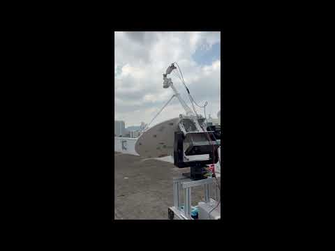
Objective
To integrate the custom-made 1 m satellite dish with the Newmark Systems NSC-G CD v1.7 gimbal, ensuring sufficient load capacity, structural stability, and reliable tracking performance.
Design Specifications
The gimbal system shall fulfil the following design requirements to ensure accurate and reliable position and heading determination for satellite tracking operations. To ensure traceability, each functional requirement was translated into measurable engineering specifications, as shown in the table below.
Requirement Traceability for Gimbal Hardware Integration
| Functional Requirement | Derived Engineering Specification | Verification Method |
|---|---|---|
| Ability to rotate in elevation for satellite tracking | Elevation axis shall achieve 0° to 85° rotation from the sky-facing position | Physical motion test |
| Ability to rotate in azimuth for target tracking | Azimuth axis shall achieve 180° rotation along the horizon without obstruction | Physical motion test |
| Ability to safely carry the payload | Gimbal structure shall support a minimum payload of 10.0 kg, consisting of 7.4 kg dish, 1.6 kg feedhorn and LNB, and 1.0 kg top plate, excluding adaptor self-weight | Static loading assessment and assembly validation |
| Maintain structural integrity during operation | Adaptor and mounting structure shall not exhibit excessive flex or wobble that affects pointing stability during motion | Visual inspection and operational testing |
| Avoid collision throughout motion range | Dish, adaptor, counterweight, and brackets shall maintain sufficient clearance from the gimbal frame and trolley across the full elevation and azimuth range | Clearance and rotation test |
| Maintain operable motor torque | Net gravitational moment about the pivot shall be reduced through counterweighting such that the motor can drive the system without stalling under normal operation | Torque calculation and motion test |
| Provide stable mounting interface | Mounting plate and bracket arrangement shall securely fasten the pivoting brackets using 4 × M4 bolts without structural failure | Bolt calculation and assembly test |
Newmark GM-12E-3A Gimbal ( NSC-G3E Stepper Motor Specifications)
| Max Output Torque | Max Payload Weight | Travel Range |
|---|---|---|
| 10.2 Nm (90 lb-in) | 23kg (50lbs) | Azimuth: ± 90° , Elevation: ±90° |
Design Considerations
Several factors were considered during the design of the gimbal integration system.
Load Capacity
The gimbal must support the combined weight of the satellite dish, feedhorn, mounting adaptor, and associated hardware. The total estimated payload includes:
-
Dish and feedhorn assembly
-
Aluminium mounting adaptor
-
Fasteners and brackets
The structural components and mounting interface were designed to ensure that the load is safely transferred to the gimbal without overstressing the mounting bolts or frame.
Centre of Mass
The satellite dish assembly introduces an offset centre of mass relative to the gimbal axis. The design ensures that the centre of mass is positioned as close as possible to the rotation axis to reduce required motor torque and improve system stability.
Clearance and Motion Envelope
The full range of motion of the gimbal was analysed to ensure that the dish does not collide with the gimbal frame and trolley structure.
Adequate clearance was included in the adaptor design to allow safe operation through the required elevation and azimuth angles.
Structural Rigidity
The mounting adaptor and support frame were designed using aluminium extrusions to provide sufficient stiffness while maintaining low weight. Structural rigidity is necessary to prevent vibration and maintain accurate satellite pointing.
Adaptor Design Iterations
During the development of the mounting adaptor, several design iterations were produced to improve structural stability, clearance, and load distribution. Each iteration addressed specific issues identified during the design and testing process.
Iteration 1: Initial Mounting Concept
Design Description
The first adaptor design consisted of a simple aluminium mounting part directly attached to the gimbal platform. The satellite dish aluminium profile was mounted directly onto this part. The space in the middle is designed to tighten bolts. The part was 3D printed first to test for fitting.
Issues Identified
-
Insufficient clearance between the dish and the gimbal frame during elevation movement.
-
The centre of mass of the dish assembly was positioned far from the rotation axis, increasing the required motor torque.
-
The dish experienced noticeable wobble when supporting the payload.

Adaptor 1 3D Model

Adaptor 1 Drawing Design

Adaptor 1 Test Deployment
Reason for Change
To improve clearance and reduce structural deformation, a revised adaptor with increased height was required. The dish’s clips were crashing with the gimbal and trolley (below).

Image showing dish crashing with the gimbal and gimbal trolley.
Iteration 2: Extended Adaptor Design
Design Description
The second iteration introduced an increase in the adaptor height to provide sufficient clearance between the satellite dish assembly and surrounding structures, particularly the dish mounting clips and the trolley frame.
An L-bracket was incorporated into the design to improve the structural connection between the aluminium profile and the adaptor plate. This increased the contact area between the aluminium extrusion and the mounting interface, resulting in improved load distribution and increased structural rigidity.
Remaining Issues
Despite the improvements, several issues were still observed during evaluation:
-
The dish assembly still collided with the corners of the gimbal structure during certain rotation angles.
-
The system was unable to achieve the required 360° rotation along the horizon (azimuth axis) due to interference between the dish and the gimbal frame.
-
Additional reinforcement was required to reduce vibration and structural flex during motion, which could affect the pointing stability of the dish.
These limitations highlighted the need for further refinement of the adaptor design to improve structural rigidity and ensure full rotational clearance.


Adaptor 2 Testing

Adaptor 2 Drawing Design
Iteration 3: Proposed Adaptor Solution
Design Description
Following the limitations identified in Iteration 2, an additional design modification was considered to resolve the remaining clearance issues. The initial proposal was to raise the entire gimbal system relative to the gimbal trolley while retaining the adaptor configuration from Iteration 2. Increasing the mounting height of the gimbal would provide additional clearance between the satellite dish and the surrounding structures, particularly the corners of the gimbal frame.
This approach was evaluated as it would allow the dish to rotate without colliding with the gimbal structure, even at extreme rotation angles.

Adaptor 3 Assembly
Design Review and Feedback
During the design review process, feedback from project and academic supervisors suggested that modifying the gimbal mounting height would introduce unnecessary structural changes to the existing system. Instead, it was recommended to increase the length of the adaptor further in order to achieve the required clearance while keeping the gimbal mounting configuration unchanged.
Increasing the adaptor length allowed the dish to be positioned further away from the gimbal structure, thereby preventing collisions and enabling the required 360° azimuth rotation.
Based on the feedback received, the design direction was revised to focus on further extending and reinforcing the adaptor structure, which ultimately led to the development of the following adaptor configuration.

Adaptor 3 Design Drawing
Iteration 4: Profile and Plate Design
Reason for Design Revision
The proposed adaptor design in Iteration 3 was ultimately not pursued due to several identified limitations.
Firstly, the dish assembly continued to exhibit noticeable structural wobble even with the addition of the L-bracket. The interface between the adaptor and the aluminium profile mounted on the dish was not sufficiently rigid. This was partly due to the aluminium profile being secured directly into the threaded carbon fibre structure of the dish, which provided limited stiffness and resulted in small structural movements during operation.
Secondly, the proposed design required machining a 420 mm aluminium component, which would lead to higher material waste and increased manufacturing costs.
Thirdly, the manufacturing process for the proposed adaptor design would have required additional machining steps and longer fabrication time. An alternative design using waterjet cutting and standard aluminium profiles available in the laboratory offered a significantly faster lead time.
Finally, and most importantly, the increased adaptor length of approximately 420 mm would significantly increase the offset distance of the dish from the pivot, resulting in a much higher gravitational moment. Based on preliminary torque calculations, the required torque would exceed the available motor capacity, making the design impractical without additional balancing mechanisms.
Profile and Plate Adaptor Design
This adaptor design was developed to address the limitations observed in the previous iterations while ensuring structural rigidity and manufacturability.
The design uses aluminium plates manufactured through waterjet cutting, which allows for precise geometry and faster fabrication. The plates interface directly with the gimbal mounting surface and the aluminium structural members, providing a more rigid and stable connection.
The adaptor assembly maintains a total offset length of approximately 410 mm, which provides sufficient clearance between the satellite dish and the gimbal structure while minimising the bending moment introduced by the offset.
The adaptor is secured using four M5 bolts arranged in a circular mounting pattern, allowing the load from the dish assembly to be distributed evenly across the mounting interface.
This configuration successfully achieves:
-
Adequate clearance to prevent collisions with the gimbal structure
-
Improved structural rigidity to minimise dish wobble
-
Reduced manufacturing cost and material waste
-
Faster fabrication through waterjet cutting and the use of existing laboratory aluminium profiles
Additional Mechanical Consideration
In addition to structural and clearance improvements, the torque requirement of the system was analysed during the design of the profile and plate adaptor.
Due to the offset distance between the satellite dish assembly and the gimbal rotation axis (approximately 200 mm), it was anticipated that the resulting gravitational moment could exceed the effective operating capability of the gimbal motor. Preliminary calculations (refer to Appendix L) estimated a torque of approximately 18–24 N·m, depending on the mass distribution of the dish assembly.
Despite this, the system was initially tested without a counterweight to evaluate the actual performance of the gimbal under load, while counterweight designs and components were being concurrently fabricated.
During testing, it was observed that the motor experienced difficulty in driving the elevation axis smoothly, with signs of increased loading and reduced responsiveness. This validated the earlier prediction that the torque demand was too high for reliable operation.
As a result, it was concluded that an additional design modification was required to reduce the effective torque acting on the gimbal motor.


Adaptor 4 Full Assembly Adaptor 4 Dish Holder Part

Adaptor 4 Assembly


Adaptor 4 Test fit using Laser Cut Acrylic and 3D printed brackets
Iteration 5: Counterweight Integration
Reason for Design Revision
Following the implementation and testing of adaptor 4 design, it was confirmed that the torque required to rotate the satellite dish assembly exceeded the operating limits of the gimbal motor.
Although prior calculations indicated that the offset load would generate a significant moment about the pivot, experimental testing without a counterweight demonstrated that the motor was unable to sustain smooth and reliable motion under this loading condition.
Design Description
To address this issue, a counterweight system was introduced on the opposite side of the pivot axis. The purpose of the counterweight was to generate a balancing moment that opposes the gravitational torque produced by the dish assembly.
The counterweight consists of four mild steel plates, each with a mass of approximately 4.66 kg, giving a total counterweight mass of 18.64 kg. Based on moment equilibrium calculations (refer to Appendix M), the counterweight was positioned at a distance of approximately 206 mm from the pivot. This arrangement was selected such that the moment produced by the counterweight closely matches the torque generated by the dish assembly, thereby reducing the net torque acting on the motor.
The counterweight was mounted using four threaded rods, allowing the position to be adjusted during assembly and testing. This enabled fine-tuning of the balance to minimise residual torque and ensure smooth operation of the gimbal.
In addition, the original gimbal base plate was replaced with a custom-designed plate incorporating four M4 mounting holes arranged on a wider bolt pattern. This modification reduced the overall weight of the system while improving structural rigidity, as the increased spacing between mounting points enhanced load distribution and resistance to bending moments.
The gimbal motor was also elevated by 90 mm to ensure sufficient clearance for the counterweight assembly, allowing the system to maintain its full range of motion without interference.

Adaptor 5 Assembly

Adaptor 5 Full Assembly Isometric View

Adaptor 5 Full Assembly Side View (90 Degrees Elevation)

Adaptor 5 Assembly, Close up
Base Plate Drawing
Top Plate Drawing
Design Considerations
Several factors were considered in the implementation of the counterweight system:
- Moment Balancing
The counterweight mass and distance from the pivot were selected based on moment equilibrium principles to counteract the torque generated by the dish. - Adjustability
A threaded rod mechanism was used to allow fine adjustment of the counterweight position, enabling precise balancing during testing. - Structural Integrity
The mounting structure for the counterweight was designed to withstand the additional loads without introducing excessive deflection or instability. - Space Constraints
The counterweight placement was designed to avoid interference with the gimbal structure and maintain full range of motion.
Outcome
The introduction of the counterweight significantly reduced the effective torque demand on the gimbal motor. As a result, the system showed improved rotational performance and reduced likelihood of motor stalling during operation.
This design iteration successfully:
- reduced the net moment acting on the motor,
- improved elevation movement performance,
- retained the clearance achieved by the profile and plate adaptor design, and
- enabled the gimbal system to operate within a more practical torque range.
The addition of the counterweight therefore formed the final mechanical improvement required to ensure that the integrated dish-gimbal system satisfied both structural and operational requirements. Refer to Appendix M for the full Torque Calculations.
System Verification
After installation, the following checks were performed:
-
Full rotation tests in both azimuth and elevation axes.
-
Verification that no collisions occur within the motion range.
-
Stability checks during movement to confirm structural rigidity.
-
Confirmation that the motors can drive the system without stalling.
The integrated system successfully achieved the required motion range while maintaining structural stability and safe mechanical operation.

Adaptor 5 Assembly

Adaptor 5 Full Assembly
Evaluation of Deliverables
The project successfully achieved the integration of the 1 m satellite dish with the gimbal system, meeting key requirements for load capacity, motion range, and structural stability. The final system achieved approximately 85° elevation travel and 180° azimuth rotation without any physical collision between the dish, adaptor, counterweight, gimbal structure, and trolley.
The final adaptor design improved structural rigidity and significantly reduced dish wobble compared to earlier iterations. The introduction of a counterweight system (18.65 kg at 206 mm) further reduced the effective torque acting on the motor. At the reference position, the counterweight generated approximately 37.70 N·m, while the dish-side assembly produced approximately 31.00 N·m, resulting in a residual torque of -6.70 N·m, indicating a slightly over-counterweighted condition.
Experimental testing showed that the system was able to rotate successfully from -90° to 90° elevation without torque-related issues. However, when rotating in the reverse direction, the system experienced torque limitations at approximately 25° elevation. This behaviour is explained by the variation of torque balance with elevation angle. At this angle, the perpendicular distance of the counterweight decreases, reducing its effectiveness and resulting in a larger residual torque on the dish side. While this torque assists motion in one direction, it opposes motion in the reverse direction, exceeding the available motor torque and causing reduced performance.
Overall, the system satisfies the primary functional and structural deliverables. However, further optimisation is required to achieve consistent torque balance and reliable performance across the full range of motion.

| Requirement | Specification | Test Method | Result | Status |
|---|---|---|---|---|
| Elevation motion | 0° to 85° elevation | Physical motion test | Achieved ~85° without obstruction | Pass |
| Azimuth motion | 180° rotation | Physical motion test | Achieved full rotation without collision | Pass |
| Payload support | Support ~10.0 kg dish-side load | Assembly and static loading | Structure stable under load | Pass |
| Collision avoidance | No interference in full motion | Full range rotation test | No collision observed | Pass |
| Structural rigidity | Minimal wobble during motion | Visual inspection | Reduced wobble vs previous iterations | Pass |
| Motor operability | Continuous motion without stalling | Bidirectional motion test | Smooth motion from -90° to 90°, limitation at ~25° in reverse direction | Partial Pass |
| Bolt integrity | Safe load handling | Appendix M calculations | Stresses within allowable limits | Pass |
Future Work
Future work will focus on addressing the observed non-uniform torque balance across the elevation range, particularly the torque limitation near 25° elevation caused by the reduction in counterweight effectiveness due to changing perpendicular distances.
To mitigate this, a dynamic or adjustable counterweight system can be developed to maintain a more consistent balancing moment as the gimbal rotates, reducing the large residual torque observed at intermediate angles.
In addition, since the current motor is unable to overcome the peak residual torque in the reverse direction, a higher torque motor or improved actuation system may be required to ensure reliable operation under worst-case loading conditions.
Furthermore, a torque–elevation model will be established to quantitatively characterise how gravitational torque varies with angle, enabling more accurate prediction of failure regions and guiding optimisation of both counterweight configuration and motor selection.